Led Driver Circuit Design

An LED is a special type of diode used as an Optoelectronic device. Like a PN junction diode, it conducts when forward biased. However, a special feature of this device is its ability to emit energy in the visible band of the electromagnetic spectrum i.e. Visible light. A major concern to drive an LED is to provide an almost constant current input.
Learn about LED circuits, simple LED circuits, and LED driver circuit. Understanding LED Application Theory And. Driving-Circuit Design. To a constant current driver and LED string. The design represents a constant current.
Often, an LED is driven using batteries or control devices like microcontrollers. However, these have their own disadvantages, for example – low battery life etc. A feasible approach would be driving the LED using AC to DC power supply. Though AC to DC power supply using transformer is quite popular and widely used, for applications like driving loads like LED, it proves to be quite costly and moreover it is not possible to produce a low current signal using transformer. Keeping in mind all the factors, here we designed a simple circuit driving an LED from 230V AC. This is accomplished using a capacitor based power supply.
This is a low cost and efficient circuit and can be used at homes. Related Post. Table of Contents • • • • • • • • 230v LED Driver Circuit Principle The basic principle behind the 230V LED Driver circuit is transformer less power supply. The main component is the X-rated AC capacitor, which can reduce the supply current to a suitable amount. These capacitors are connected line to line and are designed for high voltage AC circuits.
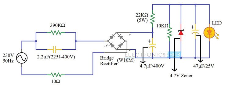
The X – Rated Capacitor reduces only the current and the AC voltage can rectified and regulated in the later parts of the circuit. The high voltage and low current AC is rectified in to high voltage DC using a bridge rectifier. This high voltage DC is further rectified using a Zener diode to a low voltage DC. Finally, the low voltage and low current DC is given to an LED. 230v LED Driver Circuit Diagram Components Required • 2.2µF Polyester Film Capacitor (225J – 400V) • 390KΩ Resistor (1/4 Watt) • 10Ω Resistor (1/4 Watt) • Bridge Rectifier (W10M) • 22KΩ Resistor (5 Watt) • 4.7µF / 400V Polarized Capacitor • 10KΩ Resistor (1/4 Watt) • 4. Scapy How To Install. 7V Zener Diode (1N4732A) (1/4 Watt) • 47µF / 25V Polarized Capacitor • 5mm LED (Red – Diffused) How to Design a 230V LED Driver Circuit?
First, a 2.2µF / 400V X – Rated Capacitor is connected in line with the mains supply. It is important to pick a capacitor with voltage rating greater than the supply voltage. In our case, the supply voltage is 230V AC. Hence, we used a 400V rated capacitor. A 390KΩ resistor is connected in parallel with this capacitor to discharge it when the supply is turned off. A 10Ω resistor, which acts as a fuse, is connected between the supply and bridge rectifier.
The next part of the circuit is a full wave Bridge Rectifier. We have used a single chip rectifier W10M. It is capable of handling currents up to 1.5 Amperes.
The output of the Bridge Rectifier is filtered using 4.7µF / 400V Capacitor. For regulating the DC output of the Bridge Rectifier, we are using a Zener Diode. A 4.7V Zener Diode (1N4732A) is used for this purpose. Before the Zener Diode, we have connected a series resistor of 22KΩ (5W) for limiting the current. The regulated DC is given to the LED after filtering it out using 47µF / 25V Capacitor.
How the 230V LED Driver Circuit Works? A simple, transformer less 230V LED Driver Circuit is built in this project. Geometry Dash Full Version more. The main components of this project are the X – Rated Capacitor, the Zener Diode and the resistor which limits the current in the Zener Diode. Let us see the working of this project. First, the 2.2µF X – Rated Capacitor (225J – 400V) will limit the AC current from the mains supply. In order to calculate this current, you have to use the Capacitive Reactance of the X – Rated Capacitor. The formula for calculating the Capacitive Reactance is given below.
So, for 2.2µF Capacitor, X C can be calculated as follows. So, from Ohm’s Law, the current that the capacitor allows is given by I = V/R. Hence, the current through the capacitor is = 230/1447.59 = 0.158 Amperes = 158mA. This is the total current that enters the bridge rectifier. Now, output of the Bridge Rectifier is filtered using a Capacitor. It is important to select an appropriated voltage rating for this capacitor. The input to the Bridge Rectifier is 230V AC, which is the RMS Voltage.